Orange Pi Zero
Description
Official website : http://www.orangepi.org/orangepizero/ (Backup)
New one : https://orangepi.com/index.php?route=product/product&product_id=844
The OrangePi Zero board is an Open-source Single Board Computer (SBC) of 48x46mm created and sold by Xunlong.
Base system
- Create initial system from scratch (sources): all the steps, using u-boot and Linux kernel sources.
- Rootfs guide to create either a minimal system using Busybox or a full Devuan GNU/Linux system.
- The "SD card creation" section from the "from scratch" page also provides information to use the u-boot, kernel image, and Devuan root filesystem I built.
You can get the images here: Images for Orange Pi Zero board.
Connection and startup
USB-UART serial console connection

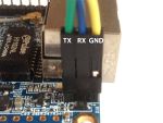
On the J3 connector (3 pins male 2.54mm, next to the Ethernet connector, pin 1 on the board edge) :
- pin 1 - GND : Black
- pin 2 - UART RX : Orange
- pin 3 : UART TX : Yellow
SD card boot
The OrangePi Zero board boots from the SD card which has to be prepared following specific steps. Follow the "SD card creation" section from the "from scratch" page
Extension ports
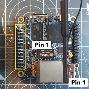
The OrangePi Zero board has two extension ports using common 2.54mm (0.1inch) pitch:
- con4 : 2x13
- con5 : 1x13

| con4 : 2x13 Header | |||
|---|---|---|---|
| 1 | 3.3V | 2 | 5V |
| 3 | TWI0_SDA / PA12 / GPIO12 | 4 | 5V |
| 5 | TWI0_SCK / PA11 / GPIO11 | 6 | GND |
| 7 | PWM1 / PA06 / GPIO6 | 8 | UART1_TX / PG06 / GPIO198 |
| 9 | GND | 10 | UART1_RX / PG07 / GPIO199 |
| 11 | UART2_RX / PA01 / GPIO1 | 12 | SIM_CLK/PA_EINT7 / PA07 / GPIO7 |
| 13 | UART2_TX / PA00 / GPIO0 | 14 | GND |
| 15 | UART2_CTS / PA03 / GPIO3 | 16 | TWI1-SDA / PA19 / GPIO19 |
| 17 | 3.3V | 18 | TWI1-SCK / PA18 / GPIO18 |
| 19 | SPI1_MOSI / PA15 / GPIO15 | 20 | GND |
| 21 | SPI1_MISO / PA16 / GPIO16 | 22 | UART2_RTS / PA02 / GPIO2 |
| 23 | SPI1_CLK / PA14 / GPIO14 | 24 | SPI1_CS / PA13 / GPIO13 |
| 25 | GND | 26 | SIM_DET/PA_EINT10 / PA10 / GPIO10 |
| con5 1x13 Header | |
|---|---|
| 1 | 5V |
| 2 | GND |
| 3 | USB-DM2 |
| 4 | USB-DP2 |
| 5 | USB-DM3 |
| 6 | USB-DP3 |
| 7 | LINEOUTR |
| 8 | LINEOUTL |
| 9 | TV-OUT |
| 10 | MIC-BIAS |
| 11 | MIC1P |
| 12 | MIC1N |
| 13 | CIR-RX |
External links
(Pseudo)random list of links to pages with information to compile u-boot, the Linux kernel, and create a root filesystem.
- Xunlong Orange Pi Wiki : http://www.orangepi.org/Docs/mainpage.html
- Xunlong Orange Pi Github : https://github.com/orangepi-xunlong/OrangePi_Build
- Linux Sunxi Wiki : Orange Pi Zero(open source software community dedicated to providing open source operating system support for Allwinner SoC based devices).
- FreeBSD : https://wiki.freebsd.org/FreeBSD/arm/Allwinner
- Armbian : https://www.armbian.com/orange-pi-zero/